Advantage
1. Meet all site test requirements. The instrument has standard four phase voltage and three-phase current output. It can not only test various traditional relays and protection devices, but also test various modern microcomputer protection, especially for transformer differential power protection and standby automatic switching device. The test is more convenient and perfect.
2. All technical indexes fully meet the standard of DL / t624-1997 technical conditions for microcomputer based relay protection test devices issued by the Ministry of electric power.
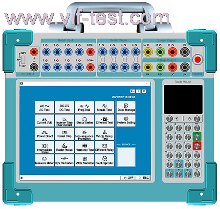
3. Classic Windows XP operation interface, friendly man-machine interface, simple and fast operation; High performance embedded industrial control computer and 10.4-inch resolution of 800 × The TFT true color display of 600 can provide rich and intuitive information, including the current working state of the equipment and various help information.
4. The native Windows XP system has its own recovery function to avoid system crash caused by illegal shutdown or misoperation.
5. It is equipped with ultra-thin industrial keyboard and photoelectric mouse, which can complete various operations through keyboard or mouse like ordinary PC.
6. The main control board adopts DSP + FPGA structure and 16 bit DAC output. It can generate 2000 high-density sine waves per week for the fundamental wave, which greatly improves the quality of the waveform and the accuracy of the tester.
7. The power amplifier adopts high fidelity linear power amplifier, which not only ensures the accuracy of small current, but also ensures the stability of large current.
8. It adopts USB interface to communicate directly with PC without any adapter line, which is convenient to use.
9. It can be connected to a laptop (optional) for operation. The notebook computer and industrial computer use the same set of software, and there is no need to learn the operation method again.
10. It has the function of GPS synchronization test. The device can be equipped with a built-in GPS synchronization card (optional) and connected with PC through RS232 port to realize the synchronous adjustment test of two testers in different places.
11. It is equipped with independent and special DC auxiliary voltage source output, and the output voltage is 110V (1a) and 220V (0.6A) respectively. It can be used for relays or protective devices that need DC working power supply.
12. It has the function of software self calibration, which avoids opening the chassis and calibrating the accuracy by adjusting the potentiometer, thus greatly improving the stability of the accuracy.
Technical parameters
1. AC current source(3*40A)
|
Single phase output(RMS)
|
0--40A/phase,Accuracy:0.2% ±5mA
|
|
3 phase parallel output(RMS)
|
0--120A/3 phase in phase parallel output
|
|
Allowable long time working value of phase curren(RMS)
|
10A
|
|
Max output power/each phase
|
420VA
|
|
Max output power when 3 phase parallel
|
1000VA
|
|
Working time of 3 phase parallel max output current
|
5s
|
|
Frequency range
|
0--1000Hz,Accuracy 0.01Hz
|
|
Harmonic time
|
2--20
|
|
Phase
|
0--360°,Accuracy 0.1°
|
2.DC Current source
|
DC current output
|
0--±10A/phase,Accuracy:0.2% ±5mA
|
3.AC voltage source
|
Single phase output voltage(RMS)
|
0--125V/Phase,Accuracy:0.5% ±5mV
|
|
Line voltage output(RMS)
|
0--250V
|
|
Output power of Phase voltage/Line voltage
|
70VA/90VA
|
|
Frequency range
|
0--1000Hz,Accuracy:0.001Hz
|
|
Harmonic time
|
2--20
|
|
Phase
|
0--360°,Accuracy:0.1°
|
4.DC voltage source
|
Single phase voltage output amplitude
|
0--±150V,Accuracy:0.2% ±5mV
|
|
Line voltage output amplitude
|
0--±300V
|
|
Output power of Phase voltage/Line voltage
|
70VA/90VA
|
5.Switching value terminal
|
Input
|
8 pairs
|
|
Idle contact
|
1--20mA,24V Device internal active output
|
|
Potential reversal
|
Passive contact: low resistance short circuit signal
Active contact:0-250V DC
|
|
Output
|
4 pairs,idle contact,Interrupting capacity:110V/2A,220V/1A
|
6.Other
|
Time range
|
1ms--9999s,accuracy:1ms
|
|
Dimension/weight
|
350 mm x 285 mm x 165mm,12.5Kg
|
|
Power supply
|
AC220V±10%,50Hz,10A fuse
|
Panel
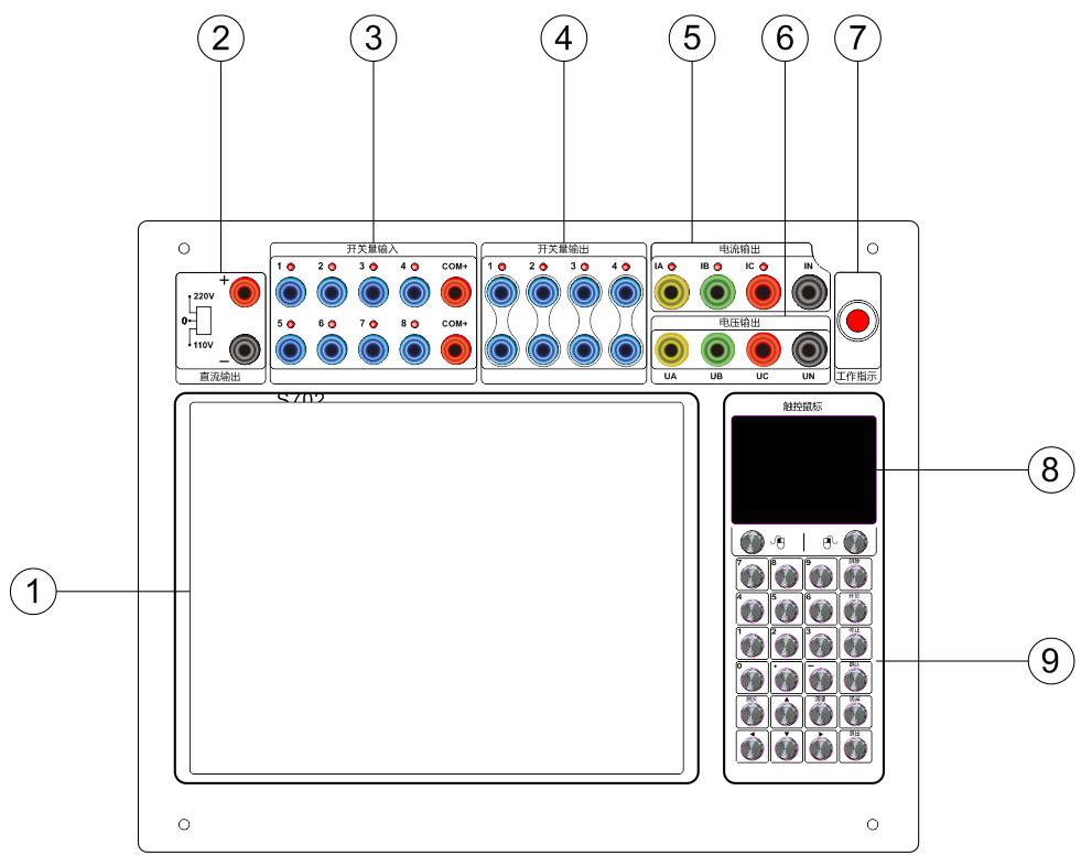
1. Display screen: 10.4-inch LED display screen.
2. Auxiliary power supply of the device: it can output DC 0; 110V;220V, power supply can be switched through the dial switch, and the maximum current output is 2A, which can supply power to the protection device.
3.Switching value input: it is used to collect the switching value signal output by the protection device and measure the time or detection signal. It can identify the active contact and passive contact. The maximum DC voltage of the active contact is DC220V. When connecting the active contact, note that + com is the positive pole of the power supply.
4.Switching value output: used to control other equipment, passive nodes, with the maximum capacity of AC220V / 1A.
5. Three phase current output terminals: IA, IB, IC, in is the common terminal, and the LED on indicates the open circuit indication of the current source.
6. Three phase voltage output terminals: UA, UB, UC and UN are common terminals.
7. LED work indication: the LED flashes to indicate waiting for work, and the LED is always on to indicate working.
8. Touch panel: similar to the touch panel of notebook computer, it can be controlled by omni-directional touch. Left and right keys: the left key is the confirmation key, and the right key can view the file properties.
9. Keyboard: used to input fixed value data, including start, end and exit shortcut keys, up, down, left and right direction keys
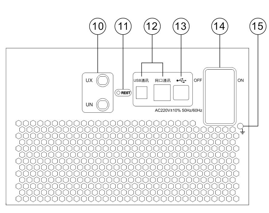
10. The fourth voltage output terminal: UX, UN is the grounding terminal.
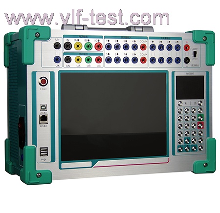
11. RST: reset button of DSP control board. When the software shows that the data transmission fails or there is no device connection, press this button to reset the DSP board, and the mark of USB device can appear at the bottom right of the screen.
12. Communication port: USB communication can be connected with an external laptop to control the operation of the instrument; Network port communication (optional), which can realize multi machine control function, or single machine network port communication to control and operate the instrument.
13. USB expansion interface: there are two USB interfaces, which can connect USB devices such as mouse, keyboard and USB flash disk.
14. Power interface: AC220V AC voltage is connected through the supporting connecting line, and the internal insurance specification is 10A, 5mm*10mm; On: power on; off: power off.
15. Grounding: safely grounded through supporting grounding wire.
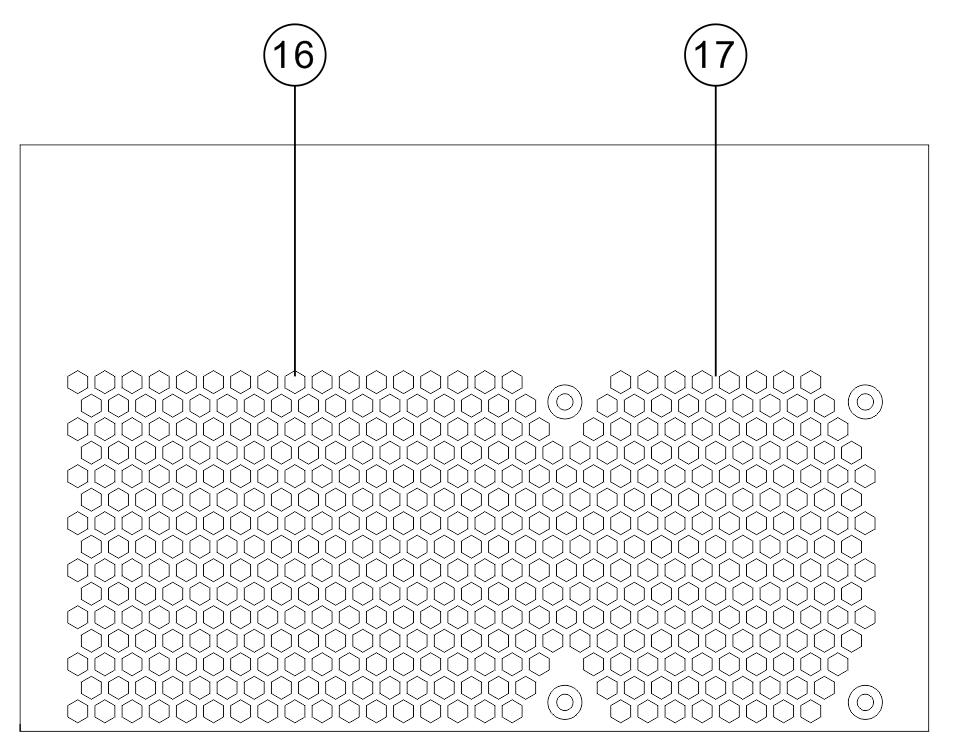
16. Side panel: heat dissipation and exhaust hole. (do not cover when using)
17. Fan exhaust hole: heat dissipation and exhaust. (do not cover when using)
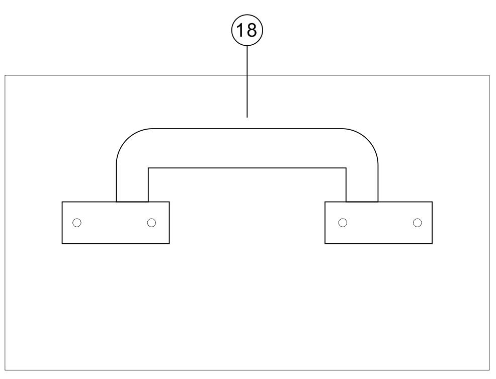
18. Handle: it is an instrument handle, which is made of metal materials and is strong and durable.
Accessories
1.Portable aluminium alloy box: 1 unit;
1.Power supply cable: 1 unit;
2.CD drive: 1 unit;
3.USB/RS232 connection: 1 unit;
4.Test cable: 1 set
5.Test clip and accessary: 1 set;
6.Fuse: 3units/10A Fuse; 3 units/2A fuse
7.Certificate: 1 unit
8.Calibration Report: 1 unit
9.Operating manual: 1 unit

 0.1Hz VLF AC/DC Hipot tester